Guide to Wire Rope
MENU
- Structural Wire Rope Applications
- Computer-Assisted Design and Detailing
- High Strength Structural Strand
- Custom Finishes
- Pre-stretching
- Striping
- Measuring Wire Rope
- Corrosion Protection
- End Terminations
- Attaching Sockets
- Proof loading
- Order Specifications
- Wire Rope Selection
- Rotation-Resistant Ropes
- Specialized Wire Rope
- Wire Rope Handling and Installation
- Standard Operating Practices
- Wire Rope Inspection
- Technical Info & Specifications
Basic Guidelines of Wire Rope Inspection
Troubleshooting Wire Rope
Abrasion
Abrasion damage may occur when the rope contacts an abrasive medium or simply when it passes over the drum and sheaves. Therefore it is vital that all components be in proper working order and of the appropriate diameter for the rope. A badly corrugated or worn sheave or drum will seriously damage a new rope, resulting in premature rope replacement.
Corrosion
Corrosion is very difficult to evaluate but is a more serious cause of degradation than abrasion. Usually signifying a lack of lubrication, corrosion will often occur internally before there is any visible external evidence on the rope’s surface. A slight discoloration caused by rusting usually indicates a need for lubrication which should be tended to immediately. If this condition persists, it will lead to severe corrosion which promotes premature fatigue failures in the wires and strands, necessitating the rope’s immediate removal from service.
Wire Breaks
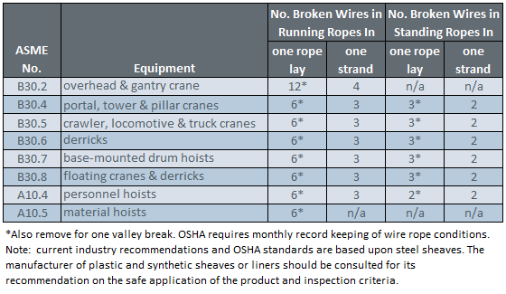
The table below shows the number of allowable wire breaks per crane type. The inspector must know the ASME standard for the equipment being inspected. The number of broken wires on the outside of the wire rope is an indication of its general condition and whether or not it must be considered for replacement. The inspector may use a type of spike to gently probe the strands for any wire breaks that do not protrude. Check as the rope runs at a slow speed over the sheaves, where crown (surface) wire breaks may be easier to see. Also examine the rope near the end connections. Keeping a detailed inspection record of the wire breaks and other types of damage will help the inspector determine the elapsed time between breaks. Note the area of the breaks and carefully inspect these areas in the future. Replace the rope when the wire breaks reach the total number allowable by ASME or other applicable specifications.
Allowable Wire Breaks

Valley breaks, or breaks in between strands, must be taken very seriously at all times! When two or more valley breaks are found in one lay-length, immediately replace the rope. Valley breaks are difficult to see; however, if you see one you can be assured that there are a few more hidden in the same area. Crown breaks are signs of normal deterioration, but valley breaks indicate an abnormal condition such as fatigue or breakage of other wires such as those in the core.
Once crown and valley breaks appear, their number will steadily and quickly increase as time goes on. The broken wires should be removed as soon as possible by bending the broken ends back and forth with a pair of pliers. In this way the wire is more likely to break inside the rope where the ends will be tucked away. If the broken wires are not removed they may cause further damage. The inspector must obey the broken wire standard; pushing the rope for more life will create a dangerous situation.
Diameter Reduction
Diameter reduction is a critical deterioration factor and can be caused by:
- Excessive abrasion of the outside wires
- Loss of core diameter/support
- Internal or external corrosion damage
- Inner wire failure
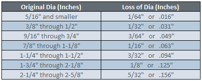
It is important to check and record a new rope’s actual diameter when under normal load conditions. During the life of the rope the inspector should periodically measure the actual diameter of the rope at the same location under equivalent loading conditions. If followed carefully, this procedure reveals a common rope characteristic—after an initial reduction, the overall diameter will stabilize and slowly decrease in diameter during the course of the rope’s life. This condition is normal. However, if diameter reduction is isolated to one area or happens quickly, the inspector must immediately determine (and correct, if necessary) the cause of the diameter loss, and schedule the rope for replacement.
Recommended Retirement Criteria Based On Diameter Reduction

Crushing
Crushing or flattening of the strands can be caused by a number of different factors. These problems usually occur on multilayer spooling conditions but can occur by simply using the wrong wire rope construction. Most premature crushing and/or flattening conditions occur because of improper installation of the wire rope. In many cases failure to obtain a very tight first layer (the foundation) will cause loose or “gappy” conditions in the wire rope which will cause rapid deterioration. Failure to properly break-in the new rope, or worse, to have no break-in procedure at all, will cause similar poor spooling conditions. Therefore, it is imperative that the inspector knows how to inspect the wire rope as well as how that rope was installed.
Shock loading
Shock loading (bird-caging) of the rope is another reason for replacement of the rope. Shock loading is caused by the sudden release of tension on the wire rope and its resultant rebound from being overloaded. The damage that occurs can never be corrected and the rope must be replaced.
High Stranding
High stranding may occur for a number of reasons such as failure to properly seize the rope prior to installation or maintain seizing during wedge socket installation. Sometimes wavy rope occurs due to kinks or a very tight grooving problem. Another possibility is simply introducing torque or twist into a new rope during poor installation procedures. This condition requires the inspector to evaluate the continued use of the rope or increase the frequency of inspection.

